I truly believe that the two best ways to learn something are by doing/using that thing or by building that thing. I was literally just scrolling twitter before bed one sunday night and I saw some game devs arguing about something. I don’t even remember what they were arguing about, but that day I realized I had never done anything with computer graphics. In my mind it was one of those “hard tech” domains of software; grouped in with operating systems, kernels and stuff. And I was also on the lookout for something exciting I could do with C++. I had learned C over the summer and the programming course in uni was in C++. So I figured why not go all-in and just build a 3d renderer! This post contains notes and stuff I learnt while building the rasterizer.
It’s a lot of unfiltered thought and some of the math may be formally wrong (beware!) but I’ve tried to leave some intuitive explanation so that I myself could implement it in code.
Drawing Straight lines
- Finally I used y = mx + c
Filling in triangles
-
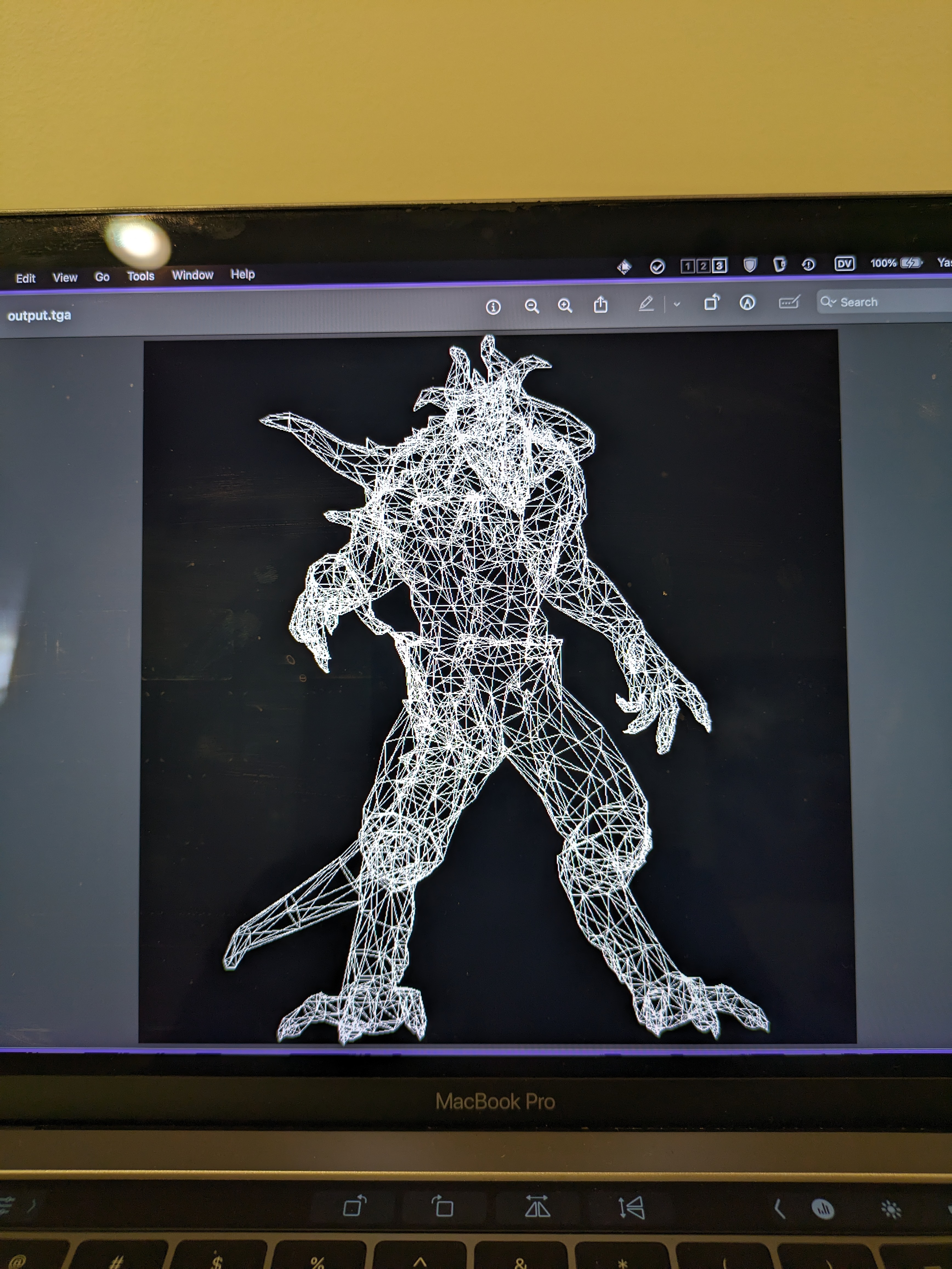
Drawing a lot of lines together, makes it look like a filled in solid.
-
But very inefficient.
-
Barycentric coordinates are superb to test whether a point is inside or outside a triangle.
-
Bounding boxes are like the rough draft we draw before drawing the actual shape.
-
After drawing bounding box, we can quickly test for each point.
-
For some reason, this is quicker than the line technique.
-
Barycentric coordinates are also very convinient for interpolating values inside the triangle.
-
They are basically weighted average of the cartesian coordinates. If you have the value of something in the vertices, the weighted average of that something is the value of that thing at the location given by the Barycentric coordinates.
Hidden face removal.
- No need to draw faces that will be hidden:
- Efficiency.
- Sometimes, by mistake, we might draw the hidden face over the actual face (depending on the order of faces in the file).
- So we need a way to determine if the said face (well pixel actually) is gonna be visible over the others.
- It’s hard to determine per faces, because some faces might overlap at multiple places.
- So F1 might be above F2 for (x, y) and below F2 for some other (x1, y1).
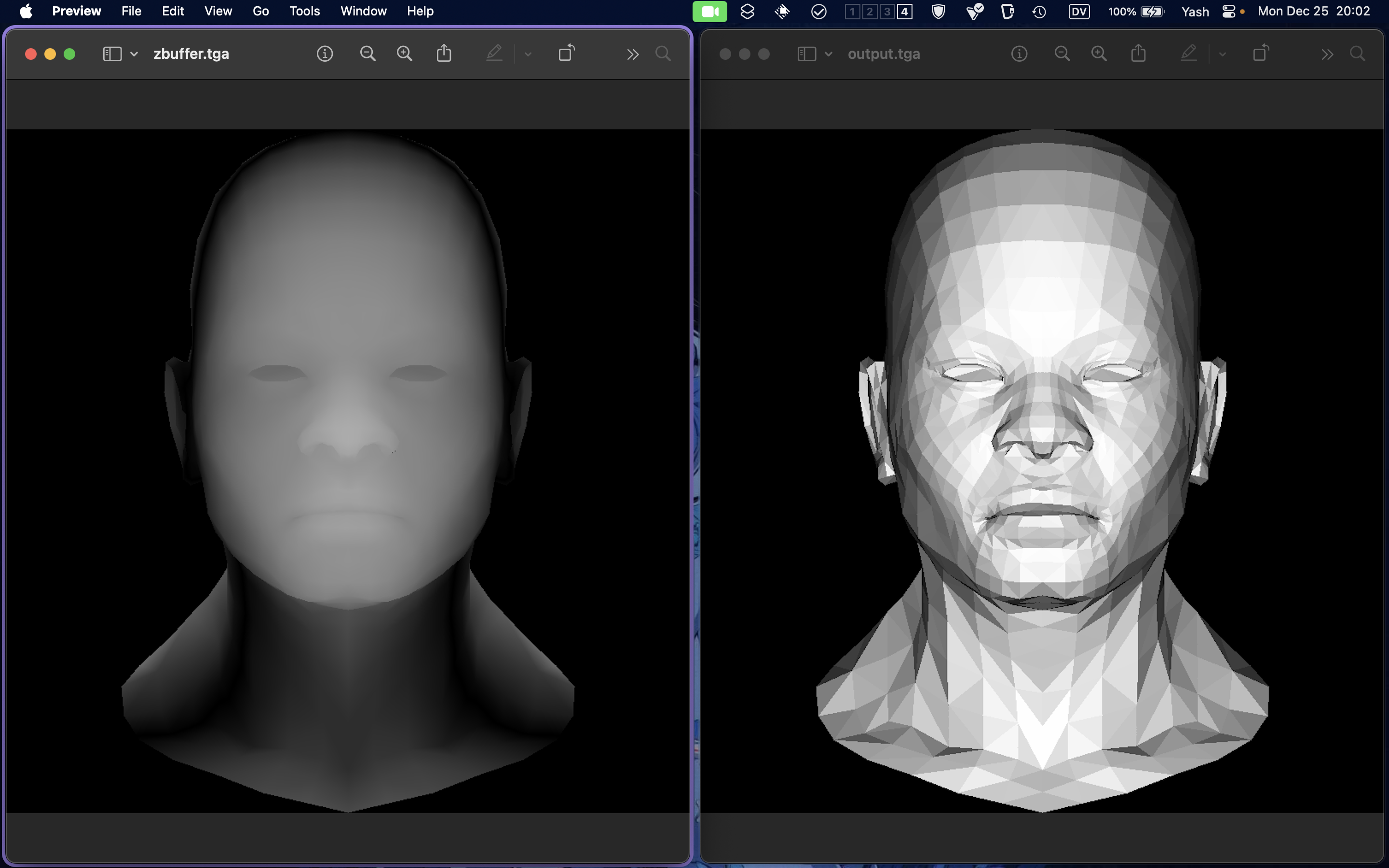
- That’s where z-buffers come in. Think of it like a topological projection of the figure onto a plane.
- We check our current pixel against the z-buffer, to check if it’s the forward-most pixel for the gives x, y coordinate.
- Related to painter’s algorithm.
Texture mapping
- Idk why it’s called texture, I just did colors.
- We have two files now:
.objand an image file that is the texture map for the object. - For each pixel in the model, we have a corresponding pixel in the texture image that tells us what the color of that pixel in the model should be.
- Calculating this stuff was painful (I should revisit).
Homogenous Coordinates
Convo with chatgpt where it finally kinda clicked.
-
Rotations, shears, scaling are linear tf so they won’t move the origin.
-
For translation, we append another transformation after performing our lin tf.
-
But this looks ugly and doesn’t let us compose all transformations into a single matrix, so we need a way to represent non-lin tf as matrices.
-
That’s where homogeneous coordinates come in: representing translation using homogeneous coordinates
-
This means our 2D plane is the z = 1 plane inside a 3D space.
-
So we do a linear transformation in 3D and then project the result back onto our 2D plane.
-
Projecting 3D onto 2D is done by dividing the components by z.
-
We embed 2D into 3D by putting it inside the plane z = 1.
-
To project from 3D to 2D, we draw a straight line between the origin and the point to project and then we find its intersection with the plane z = 1.
-
The intersection point is the projection of that point onto 2D.
-
What about division by zero?
- The projection basically projects (x, y, z) in the direction of (x, y) but onto z = 1. If the z is very small, the point basically gets projected in the direction of (x, y), but intersects z = 1 at a point infinitely far away.
- So the thing is basically a vector pointing in (x, y).
ModelView matrix
-
This matrix is used to transform vertices of 3D objects into the camera’s view space.
-
Multiplying a vertex with this matrix will bring it into view as seen from the perspective from the specified “eye” position.
-
This is cuz the renderer itself has no concept of camera. But we can simulate one by transforming the scene in the opposite direction giving the illusion that the scene is being view from a different point.
-
The matrix is an inverse matrix (Minv) cuz the transformation is gonna transform the “scene in the opposite direction”.
-
Read up on change of basis. We can figure out a formula for calculating (x’, y’, z’) of the object w.r.t the alternate basis.
Shaders
The part that calculates lighting, color and stuff for a scene.
Vertex shader:
-
Transfroms scene using ModelView and other matrices.
-
Calculates the varying values (
varying_intensity) at each vertex. Fragment shader: -
Calculates color and lighting conditions for each pixel by extrapolating from the varying values.
-
Data returned from the fragment shader is passed into the rasterizer which actually sets the color of the pixel.
Other resources:
- My rasterizer
- Tinyrenderer - Ssloy
- Raytracing in one weekend
- Scratch a Pixel blog
- Graphics in 5 minutes
- UW CS488 lecture slides
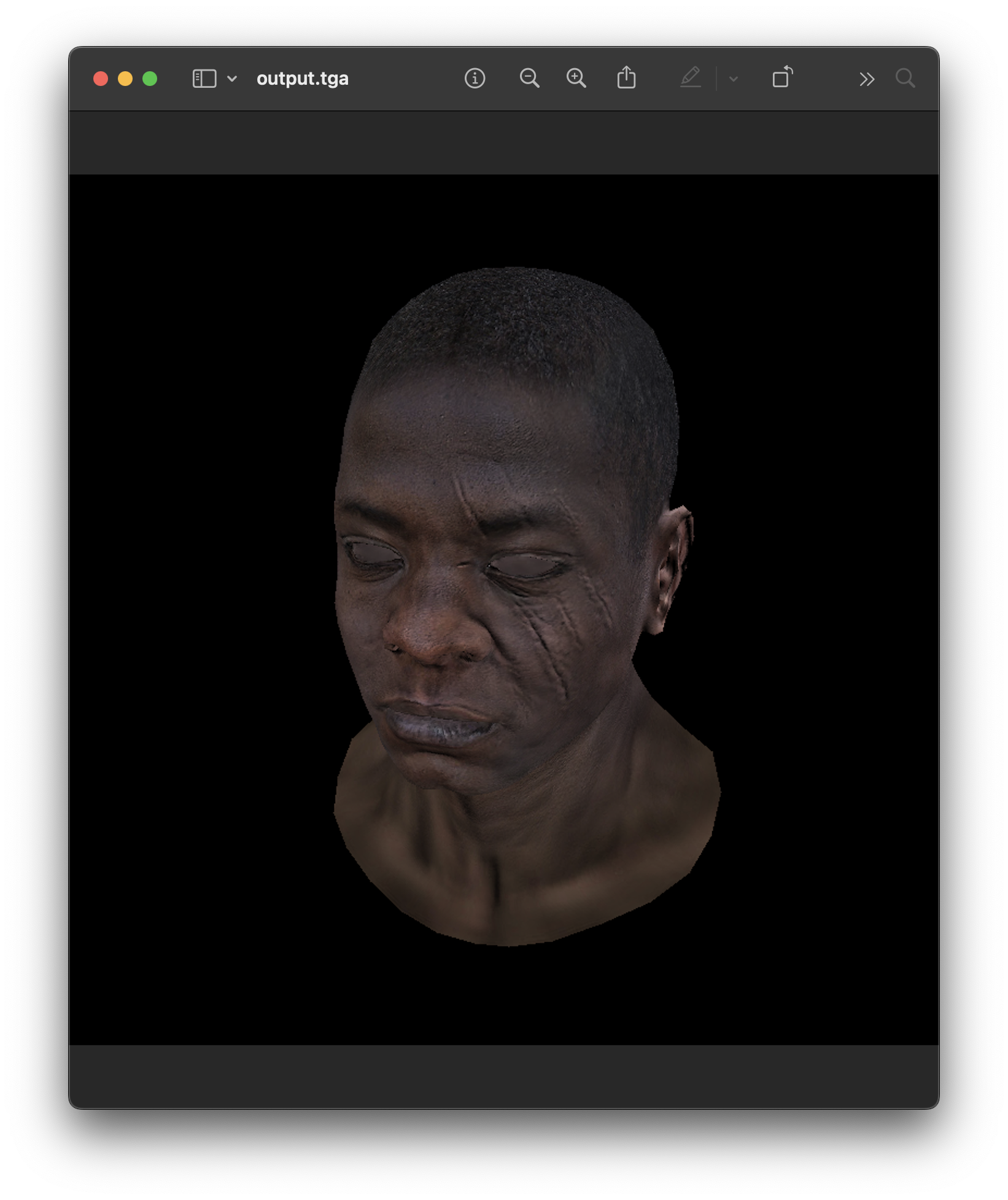
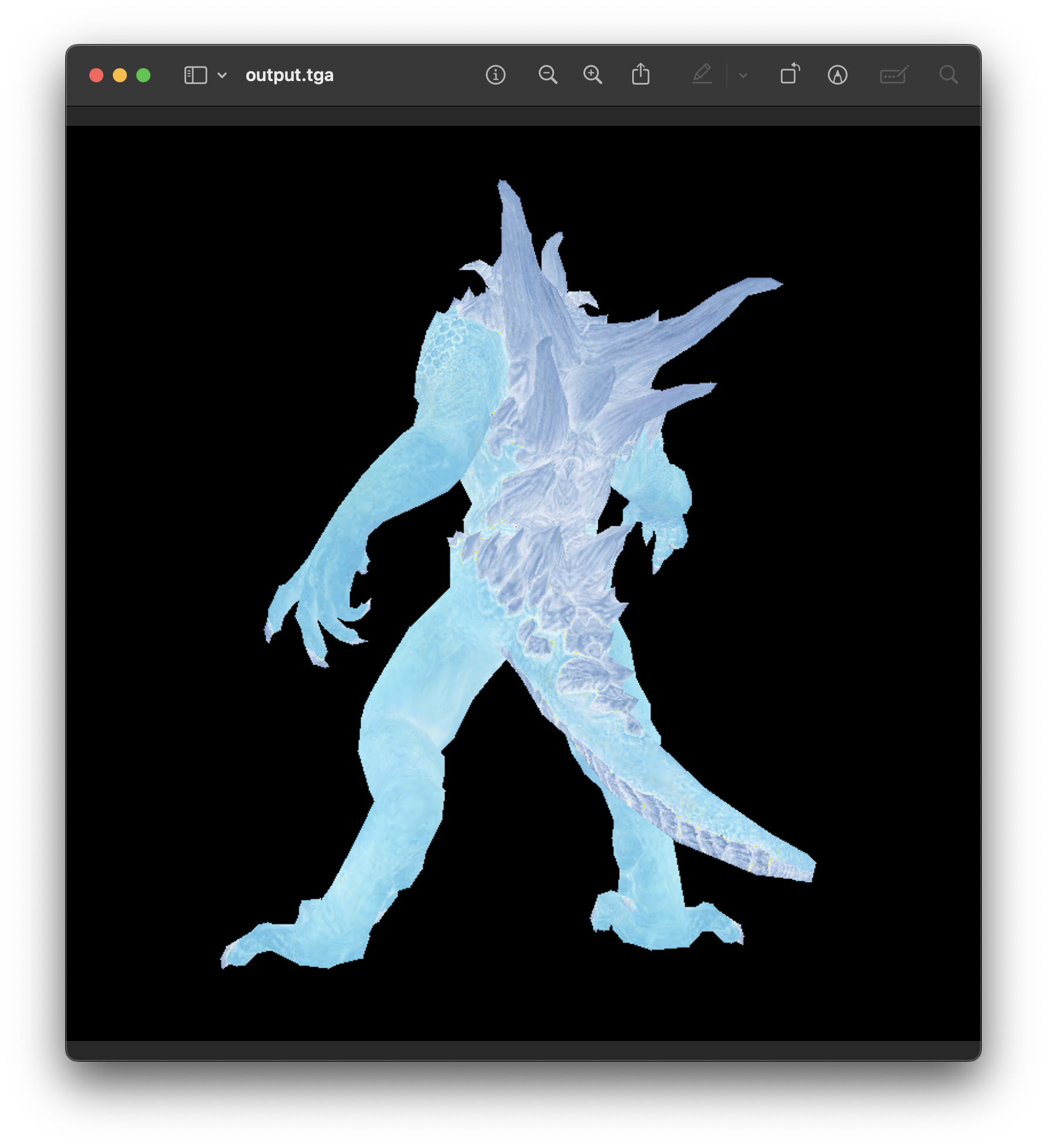
Some Images: